Project Summary
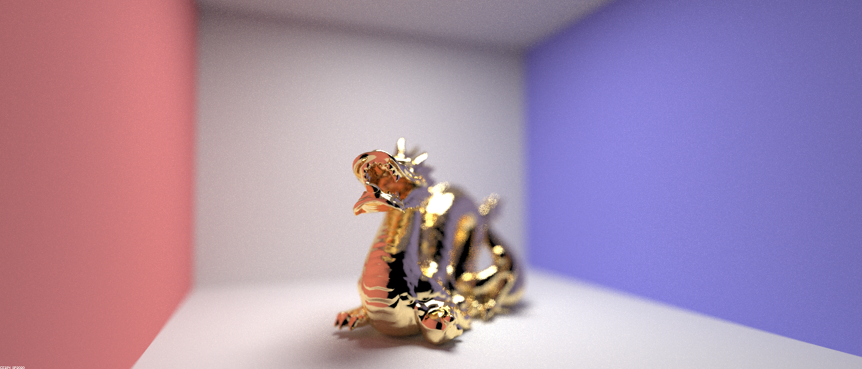
This is a really cool assignment from CS 184, Computer Graphics, at Berkeley! In this project, I implement the BSDFs for mirror and glass materials (functions that simulate how light bounces off, diffuses from, or refracts within different materials) as well as a depth of field effect - all accomplished through ray tracing. Check it out!
Part 1: Mirror and Glass Materials
This part focused on implementing the general reflecting and refracting property of materials - defining the behavior of a ray when it hits a material surface. In computer graphics, this behavior is defined by a BSDF function unique to every material. Given an incident ray, the BSDF outputs a random outgoing ray direction and the probability this was the outgoing ray resulting from the incident ray.
For perfect mirrors, given an incident ray, there is only one possible outgoing ray: the ray resulting from reflecting the incident ray across the surface normal. Thus, for the mirror BSDF, we implemented a sampling function that given an incident ray upon the mirror surface would return the ray reflected across the surface normal with 100% probability.
Next, for glass, both reflection and refraction occur when light hits the surface. To implement refraction, we consider if the incident ray is entering or exiting the non-air medium. Based on whether or not it is exiting, we calculate η to be the ratio between the origin medium and the destination medium. Using η we can directly calculate each of the outgoing ray's components. Before we return these calculations, we also check whether or not the ray undergoes total internal reflection, in the case in which the light ray is unable to escape the origin medium and is refracted back inside. Finally, to account for both reflection and refraction in glass' BSDF function, we use Schlick's approximation, choosing to return a refracted ray with some probability R and the perfectly reflected ray with probability 1-R, scaling each ray's returned probability respectively.
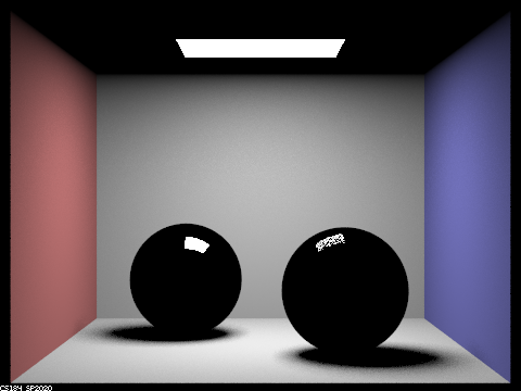
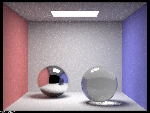
0-bounceOnly light from light sources can reach our viewpoint in 0 bounces.

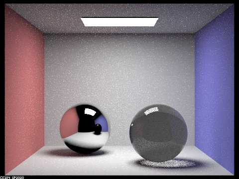
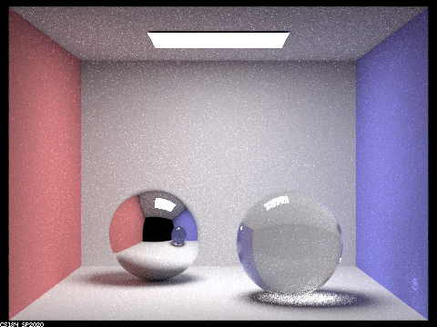
We can now see the walls and the direct spots at which light has been reflected off of the balls. Notice that the light spot on the glass ball is grainy - this is because only some light from the light source that hits the ball is reflected, the rest is refracted through the ball and incapable of reaching our view point in 1 bounce. Also the ceiling is dark because no light has been bounced off the ceiling yet from our scene.
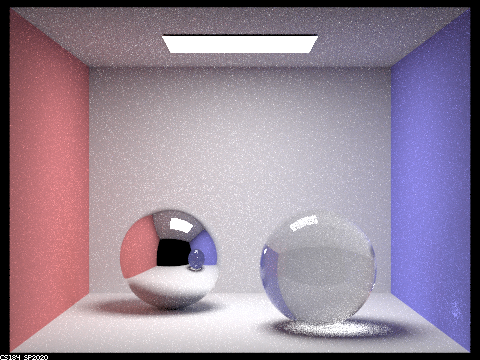
Now we can see light that has been reflected off different surfaces off the mirror ball into our view point. We can also see light that has been refracted through the glass ball onto the ground into our view point. The ceiling is now lit up by light from different surfaces as well. This is the first image in which we see light in the shadow of the glass ball. This is light that has come from the light source, refracted through the ball, bounced off the ground and into our view point. Finally, the glass ball is slightly brighter because refracted light has been able to enter through the ball and exit into our view point. We can see the glass ball looking dark in the mirror ball because the image on the mirror ball must be 1-bounce only.
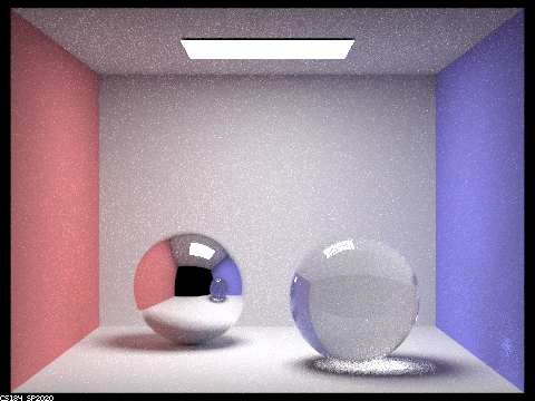
More light from the scene enter into the glass ball and is able to be refracted out to our view point, making the ball appear lighter to us. It seems as though light from the upper right hand corner of the room is finally refracted through the glass ball at this point: one bounce off the ground, onto the upper right hand corner, into the glass ball and out towards our view point.
More light from the scene enter into the glass ball and is able to be refracted out to our view point, making the ball appear lighter to us. A small bright splotch on the right of the purple wall appears since the glass ball is appearing significantly bright enough in contrast to environment lighting.
Part 4: Depth of Field
Originally, we had a camera in which we sample several light rays within the area of an image associated with a pixel on the sensor. Now we've introduced a lens into the camera which slightly refracts the direction that a ray originating from the image goes towards on the camera sensor. We imitate the sampling of light through the lens by randomly sampling points in the lens area that a light ray from the image would hit. After we determine the point on the lens that the light ray hits, we can calculate the point on the focal point of the camera lens that the light ray would intersect. This is what appears on the sensor of the camera. The random sampling of a wide range of light that is capable of hitting our camera lens for a specific pixel value on our sensor is what causes the depth of field effect.
How does a pinhole camera model differ from the thin lens camera model?Pinhole cameras allow very few and specific rays of light to be exposed to a point on the film since light travels in lines and only a few of these lines pass through the pinhole, whereas lens allow multiple rays of light to be focused onto a point on the sensor. However, since the pinhole camera doesn't have a focus (theoretically it can capture every ray in a scene and expose it to a sensor large enough), it has infinite depth of field, everything will be in focus given enough exposure time. On the contrary, only light from regions that are refracted into the focal point of the lens will be perfectly in focus, the area of the sensor away from the focal point will be more and more out of focus - receiving light from different parts of the scene. Lenses tend to gather more light rays from a specific point in the scene which are then focused onto the respective point on the sensor and thus need a much shorter exposure time for a bright image (pinhole camera images tend to be darker since less light is gathered per unit time).
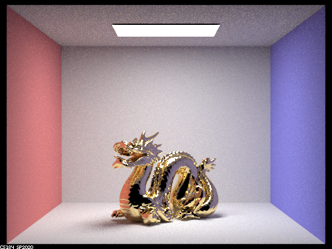
Focus stack of 4 different focal distances.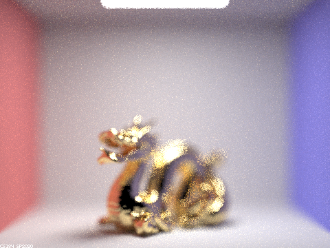
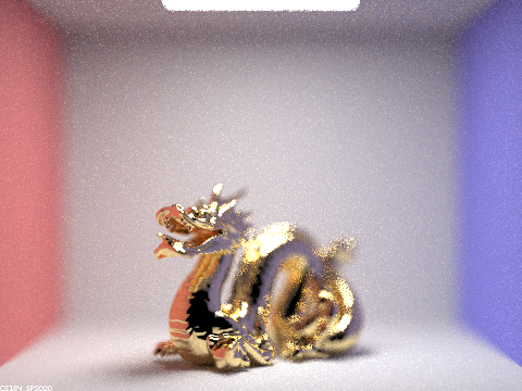
We can see that as the focal distance increases, we transition in focus across the head of the dragon to the tail, as the head is closer to our view point than the tail.
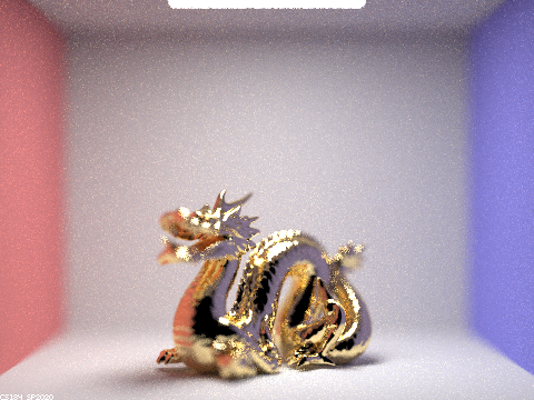
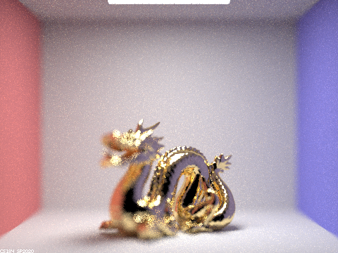
Stack of 4 different apertures.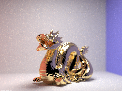

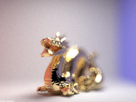
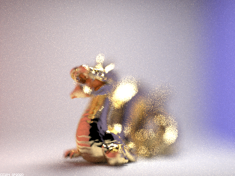
As we increase the aperture (lens radius), the depth of field gets smaller or the amount of the picture in focus gets smaller and the blur gets stronger as we depart from the area of focus (the chest area of the dragon at a focal distance of 2.7).
Conclusion
This was such a fun project. It's actually so crazy how many light rays computers can simulate, and it's so crazy how close to real life these objects look, and it's so crazy that we can model materials with mathematical formulas! It's unfathomable and awe-inspiring just how much computation makes up the reality we live in today. Just want to share some quick stats on exactly what it took to render the header image at the top of this page:
Input:- 4-core i5-6300HQ
- 128 light ray samples per pixel
- 4 samples per light
- Maximum ray bounce depth of 7
- 1680 x 720 image resolution
- 11.5 minutes to render
- 2.5 billion light rays traced
- 3.7 million light rays per second
I'm really interested in how ray tracing is sped up to eye-level speed utilizing GPUs for video games. Ray-traced VR is literally a simulation of real life! On a side note, let me know if any of the intuition on this page is wrong - I'm still a little unsure about the light bounce behavior (it twists my head in knots like most recursive things). Thanks so much for tuning in! ✌️